How to wire your Digi I
Since I got my car running on Digi I, I have had a number of people asking what wires to hook up where to convert their systems over to Digi. I have s few pictures taken while converting my 87 Scirocco 16V CIS-KE system over. I hope this will clear up any questions.
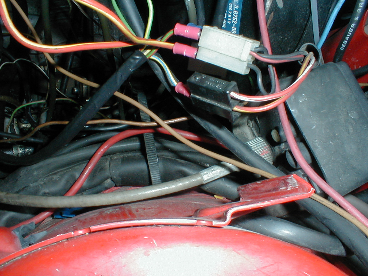
Ok, there are three plugs that hook the CIS harness up to the car harness. On the Scirocco, they are located by the firewall next to the brake booster. The A2's should be similar, when you take the old harness out, it should have about similar connections. It helps to pull the coolant bottle out of the way for better access. As you can see in the picture below, two of the plugs are visible. There is a third plug (A/C request green wire and canister purge, blue wire) underneath the white 3 wire connector and the black 2 wire connector.
The white 3 wire connector is the source of key-on power for the Digi computer. There are only two wires going to the three wire connector, but the black wire loops back for the third spot. These two black wires are key-on power. On my car I plugged the black with a yellow stripe power feed into one of these spots. The other black wire in this connector was used to provide power to the injectors and has the Large gauge red with a yellow stripe wire plugged into it. On a stock Corrado, this wire was connected to the fuel pump circuit and only got power when the fuel pump relay was turned on. I really didn't want to run a wire to the back of my fuse panel, so the extra key on power wire (black) was the logical choice.
The other wire going to the white 3 wire connector is red with a black stripe. This a crank signal wire. It only gets power when the key is in the start position. I plugged the red wire with a green stripe from the Digi harness into this spot.
The Black 2 wire connector is the fuel pump relay and Heated oxygen sensor power feed (which I think is tied to the fuel pump circuit and only gets power when the relay is turned on, if it is it would be a good hook up for the injectors instead of key on power). The red with a yellow stripe is the ground controlled side of the fuel pump relay. This needs ground to turn on the fuel pump relay. This wire is a different color depending on build date of your harness. The harness I used was an early one and had a yellow wire with a blue stripe. I plugged his into the red wire with a yellow stripe in the black 2 wire connector. The other wire is not used unless you retain the heated Oxygen sensor. It is red wire with a white stripe.
There are two other wires in the Digi I harness that I have not hooked up yet, and really can be left undone. One is green wire and I believe it to be an A/C request line. It gets power when the A/C compressor is turned on and increases the idle speed to prevent stalling. The other wire is green with a yellow stripe. I believe it is the Malfunction Indicator Light driver, or MIL. It will show diagnostic trouble codes when the system is in limp mode. It is very limited and I have yet to find any info on accessing the codes.
Ok that does it for power connections. There are two ground wires that need to be hooked up on the Digi system. One is brown with a white stripe. It should be hooked up to the ground spot on the Head. The 16V motors have a stud in the back of the intake manifold where a ground stripe from the coil is hooked up. I put my ground there. While you have this ground off, it would be a good idea to make a ground strap and run it from the negative battery terminal to this ground stud on the intake. This is a big reason 16v motors crank while cold but will not start. They will crank normally meaning not slow, but as you release the starter they will sometimes start. This is caused by the starter pulling the ground away from the distributor sensor ground wire. It makes no spark because the sensor has no ground. I learned this the hard way along with the lesson that you never try to push start a VW in reverse. I had this problem and was late to work one day, let the car roll backwards down the driveway and let clutch out in reverse. The reverse countershaft pushed itself out of the case making a very bad noise and letting all the gear oil out on my driveway. I also learned a few swear words that day....
The second ground wire is brown with a black stripe. It hooks up to the negative side of the battery.
I hooked the coolant temp plug into the factory 16v sensor. The Digi plug will plug in and the sensor is electrically identical to the Digi sensor.
There are three more connections that need to be hooked up. There is a green wire that plugs onto the negative side of the coil. There is also a red wire with a black stripe from the car harness that hooks to the negative side of the coil, this is used for the tachometer, MFA and fuel pump relay (only on A1 cars). There should be a black wire that hooks up to the positive side of the coil (terminal 15). You should use the wire that was originally hooked up to the positive terminal of the coil.
The last connection is the oxygen sensor wire. There are 4 wire going to the Corrado O2 sensor wiring plug. Two wires in this harness are power and ground for the heater circuit. The other two are purple and black with a green stripe. The purple wire is the signal wire from the O2 sensor. The black wire with a green stripe is a sensor ground, I left mine hanging. Since my car is turbocharged, I put a O2 bung on the downpipe just after the turbo. Since it is so close to the turbo, a non-heated O2 can be used. I used a single wire O2 sensor for a 84 rabbit. you can get one of these from checkers for under 30 bucks.
All the other plugs should plug into the respective components. Plug the distributor in, the ISV ( you must have a two wire ISV, the CIS looks like the same thing but uses three wire, a Digi II donor can be used), the coolant temp, the Co pot and throttle switches and you are done.
Wiring
Black/yellow key on power
Red/green starter
Yellow/blue fuel pump relay early
Red/yellow small wire fuel pump relay later
Red/yellow large wire key on power to injectors
Green small wire A/C request
Green/yellow MIL
Green large wire Negative coil
Purple Oxygen sensor
Brown/white Ground to cylinder head
Brown/black Ground to Negative battery terminal.
If you go to SNS's website, you can find a pin-out chart and diagram for the Digi I systems. They burn awesome chips and are great to work with, hit their site and buy a chip for your Digi system here. www.snstuning.com
Tune-up and Adjustments
The Co potentiometer should be adjusted to around 450 ohms depending on modifications. The sensor should be disconnected and the meter leads should be hooked up to the two outside terminals.
Base Timing and Idle
Disconnect the coolant temp sensor after the motor is at operating temperature while the engine is running. Raise the rpm to over 3000 and drop to idle three times. This will put the motor in base timing. Using a timing light and adjust base timing to spec. Stock is 6-8 degrees btdc. You can vary this setting to match your setup and driving style. I was pinging at 7 degrees, so I am running 4-5 degrees.
Happy swapping, good luck and watch out for detonation!
January 10th, 2004